


The Baltimore & Ohio Railroad Museum is at 901 W. Pratt St, Baltimore, MD.
The museum is open year round (weather permitting) Monday-Saturday 10.00am-4.00pm and Sunday 11.00am-4.00pm, except Easter Sunday, Memorial Day, Independence Day, Labor Day, Thanksgiving, Christmas Eve, Christmas Day, New Years Eve and New Years Day.
There is so much in the collection that I have broken my photos of it into two separate pages on this website. This page features locomotives in the museum yard and car shop. The B&O Museum Roundhouse page includes locomotives and other historic artefacts on display in the roundhouse.


#1309 was one of ten 2-6-6-2 H-6 class locomotives built by the Baldwin
Locomotive Works in Eddystone, PA, in
1949 for the Chesapeake & Ohio Railroad. It was actually the last Mallet ever constructed in the US, and the last domestic steam locomotive built by Baldwin. It cost $207,129.12.
#1309 was built to a design refined by the C&O beginning with its first 2-6-6-2, H-1 #751 (renumbered #700 in 1915, and #1295 in 1924) built by Alco in 1910.

From the early 1900s into the 1920s, large numbers of Mallets were produced for US railroads. They could double the tractive effort available from non articulated locomotives and eliminate the need for double heading.
The C&O acquired the largest fleet of articulateds than any other US railroad, mainly because of the nature of its core business: hauling heavy coal trains over the Allegheny Mountains to the east coast, requiring drag power rather than speed.


When the last ten were delivered in 1949,
the C&O owned two hundred and fifty-one
2-6-6-2s.
A Mallet locomotive reuses steam from the first set of cylinders in larger, lower pressure cylinders, at the front of the locomotive. This process, called compound compression, was first applied commercially by the Swiss engineer Anatole Mallet (1837-1919) in 1876 to small, 2 cylinder 0-4-2 tank locomotives for the Bayonne-Anglet-Biarritz Railway in France.
The H-6 is also articulated, another innovation introduced by Mallet: the rear engine is attached to the frame of the locomotive, while the front engine rides on a truck attached to the rear frame by a hinge so that it can swing from side to side as it handles curves.

However, Mallets were complex engines, requiring specialist engineering skills and were not popular with all railroads.
#1309 is 98' 8¼" long from coupler to
coupler and weighs a total of 658,800 lbs (engine and tender light). The engine weighs 449,000 lbs, 376,500 lbs on its 56" drivers. Both sets of drivers had roller bearings
and forced lubrication. They are fitted
with Walschaert valve gear and the cylinders
are 22" x 32" (rear high pressure) and
22" x 35" (front low pressure). All piston valves are 12" in diameter.
With a 72.5 sq ft grate area, 370 sq ft firebox and combined heating surface of 5,877 sq ft, including 25 sq ft of arch tubes and 975 sq ft superheating, it operated at a boiler
pressure of 210 psi delivering 70,773 lbs tractive effort.

The brake system air pumps, which were mounted on either side of the front of the engine's smokebox necessitated a relatively narrow smokebox door.
This arrangement, also known as "flying air pumps", along with the pilot mounted headlight and low-slung General Steel Castings pilot give #1309 a typically Chesapeake & Ohio look. The view above also clearly illustrates why this type of front end number plate was often referred to as "frogs eyes".
Other features characteristic of the Chessie Railroad's modern steam motive power are #1309's relatively roomy cab and its over-sized box-type sand domes.


The original tenders supplied with the ten H-6 locomotives had a water capacity of 12,000 gallons of water and 16 tons of coal. The tender now attached to #1309 appears to have been swapped out from another locomotive: it has a 12,000 gallon water and 15 ton coal capacity.
All ten of the new 1300s went directly to the Logan, WV, coal district, working out of the Peach Creek Terminal. Fifteen more were planned for construction but the order was postponed and
then cancelled by the railroad because of a coal strike.


Like many locomotives built in the 1940s, with the onset of dieselisation in the post-war years, the H-6 had a short service life.
Top view above, this view from the
engineer's side of #1309 shows the underside of the deck apron (top), the stoker feed connection (centre) and radial buffer (bottom). #1309 was fitted with a Standard HT Stoker, which could deliver up to seven tons of coal per hour.
Lower view above, the over-fire jets fitted to the firebox viewed from the engineer's side of the locomotive. Each jet had a small steam nozzle to shoot a jet of steam that drew in external air and shot it into the firebox just above the fire to aid combustion. Operated by the fireman, the jets also helped reduce smoke exhaust in built up areas and engine houses.


Above, the injector overflow pipe and spreader on the engineer's side.
The last of the H-6 class was retired in 1957. #1309 was retired in 1956 and remained in the Peach Creek Terminal Roundhouse until donated to the museum in 1972.


Above top, the hinge that connects the rigid frame with the front engine frame. The steam supply pipe from the rear cylinders has been cut (centre).
The steel springs on the left compensated as
each frame tilted independently on
curves.
Both sets of drivers have a 10' wheel base, the engine wheelbase is 48' 10" and the total wheelbase is 87' 10".


Above, the brake hose pipes are flexible between the two frames. The lever in the upper part of the photo transfers the reverse gear to the front engine.
Below, the hinge connecting the front and rear frames is held in place by a rod secured by a cross pin.


On the right above, the remains of lubricating pipes for the hinge.

Above, three views of the steel plate on which the boiler slid over the front frame as the engine passed through curves.


Above, compensating devices kept lateral movement of the front engine across the slider plates under control.


Above, the main steam supply pipe from the rear high pressure to the front, low pressure cylinders had also been severed. As this and the front cylinders were part of the swivelling front engine frame, there was no need for this to be a flexible joint. Note the flattened smokebox floor, which provides room for the steam supply pipe.
Only one other H-6, #1308, has been preserved. It is now on display in Huntington, WV, and you can see photos and find out more about it on the Collis P. Huntington Railroad Historical Society page of this website. Since these photos were taken, in mid 2014, #1309 was moved to the Western Maryland Scenic Railroad's shops in Ridgeley, WV, for restoration. The locomotive is expected to be operational by May 2016.


#2705 is the second earliest survivor of the first
fourteen Berkshire type (2-8-4) locomotives built for the Chesapeake & Ohio at Alco's Schenectady, NY, works
in 1943 (#2700-#2713). You can see the first of this
order on the CO #2700 page of this website and another from it, #2707, on the Illinois Railway Museum Yard
page.
The name "Berkshire" was given by the Boston & Albany, the railroad that tested the prototype locomotive with this wheel arrangement, appropriately numbered #1, in 1925 over a division that crossed the Berkshire Hills in Massachusetts.

An impressive test occurred on 14th April 1925, when a Class H-10 2-8-2 set out from the B&A's Selkirk Yard hauling a forty-six car, 1,691 ton train. About forty-seven minutes later, #1 set out with a fifty-four car, 2,296 ton train in the same direction, arriving at North Adams Junction ten minutes before the H-10. Soon after, the B&A ordered forty-five more of the type.
Amongst other orders were fifteen for the Pere Marquette in 1936 and twelve more in 1940, as well as fifteen for the Nickel Plate in 1934 and fifteen in 1942. By then, both railroads, like the C&O, had joined the Van Sweringen stable.

The 2-8-4 was produced by the Lima Locomotive Works seeking to improve on the speed and horse power of the USRA Mikado (2-8-2) type.
Lima's Engineer William E. Woodward based the design on a New York Central Class H-7 Mikado to which he added a larger firebox, thereby creating a new Class
H-10. He then designed an even larger, 100 sq ft firebox, which required a four-wheel trailing truck to support it. The resulting 2-8-4 demonstrator was designated Class A-1 by Lima.
Lima then sent its Class A-1 demonstrator across the country and, wherever it went, the locomotive set new records. The prototype 2-8-4 was later sold to the
Illinois Central as part of an order for fifty Berkshires
in 1927, when it became IC A-1 #7049. The design
was improved over the years and, eventually, between 1926 and 1949, a total of six hundred and eleven of
the type were built for US railroads by Lima, Baldwin
and Alco.

The C&O watched development of the 2-8-4 on the two railroads through the "Advisory Mechanical Committee" which was common to the Van Sweringen railroads.


The C&O then based its K-4 design on the NKP and Pere Marquette Berkshires, but the new design had improvements such as cast steel frames with integral cylinders, although war shortages meant economies had to be made, including steel bells instead of the usual brass. After the war, brass bells were retrofitted to the locomotives.
There were inevitably problems for other railroads, of course, with the designation "Berkshire", and the locomotives were known as "Kanawhas" on the C&O, named after the river that cut through the railroad's operational heartland in West Virginia.

The K-4s were also known as "Big Mikes" by Chessie engineers because they were essentially a larger version of the USRA "Mikado" design.
The first batch of Kanawhas were bought by the C&O to meet the fast freight schedules demanded by the war-time effort, but they were very powerful and considered all-purpose engines capable of hauling heavy coal and freight, as well as passenger trains.
The locomotives operated over most of the C&O system, and the railroad rostered the largest number of the
2-8-4 type in the US, eventually acquiring ninety between 1943 and 1947, twenty from Lima and seventy from Alco.


Above, the fire grate and shaker bars. With a 90 sq ft grate area, 462 sq ft firebox and a total heating surface of 4,775 sq ft, including 122 sq ft provided by two thermic syphons and arch tubes, and 1,930 sq ft superheating, the K-4 operated at a boiler pressure of 245 psi delivering 69,368 lbs tractive effort.
The first Kanawha was retired in 1950, possibly as a result of a collision, but the remaining eighty-nine were not far behind. All had been retired by 1957 and the majority had been scrapped by 1961.


#2705 was retired to Russell, KY, in 1955 and was donated to the Baltimore & Ohio Railroad Museum in 1972.
The K-4 had a driver wheelbase of 18' 2". The engine wheelbase was 42' and total wheelbase was 93' 2".
They were equipped with Baker valve gear. All engine axles had roller bearings, and the trailing truck had Timken roller bearings. Feed water heaters were Worthington Type 5½ S SAs, and Standard HT automatic stokers fed the firebox.


Above, the trailing trucks had booster engines to aid traction on starting as well as on heavy grades, boosting tractive effort to 83,750 lbs.


Above, the tender was a cast steel water bottom design, with a capacity of 30 tons of coal and 21,000 gallons of water. It rode on two Buckeye Steel Casting Company six wheel tender trucks.
As well as #2705, eleven other "Kanawhas" have survived. You can see #2700 on the CO #2700 page of this website, #2707 on the Illinois Railway Museum Yard page, #2716 on the Kentucky Railroad Museum page, #2727 on the National Museum of Transportation, St. Louis Train Shed page, #2736 on the National Railroad Museum page and #2789 on the Hoosier Valley Railroad Museum page. #2732, #2755, #2756, #2760 and #2776 each have their own page.


Conceived as a celebration of the nation's
bi-centenary, between April 1975 and December 1976, seven million people visited the train during its tour of the forty-eight states, and tens of millions saw it pass by.
The train consisted of ten display cars converted from New York Central and Penn Central baggage cars and carrying more than five hundred exhibits of Americana, including a copy of the US Constitution, Judy Garland's dress from The Wizard of Oz (1939) and Martin Luther King's robes.
Like much of the contents of the train, the decoration graphically brought the country's Bicentennial celebration to life.
Thirty T-1s were built by the Reading from converted I-10s. They weighed 441,300 lbs, 278,200 lbs on their 70" drivers. The grate is 94.4 sq ft and the firebox 465 sq ft. With 27" x 32" cylinders and total heating surface of 6,134 sq ft, including 1,214 sq ft superheating, they operated at a boiler pressure of 240 psi delivering 67,984 lbs tractive effort. Trailing-truck boosters added 11,100 lb to starting tractive effort.
#2101 was originally built by the Baldwin Locomotive Works in 1923 as Reading Class
I-10 Consolidation
(2-8-0) #2021. It was rebuilt by the Reading in 1945 as Northern
(4-8-4) type T-1 #2101.
This was the first of three locomotives restored to haul the twenty-six car 1975-76 American Freedom Train.


The other two locomotives were former Southern Pacific 4-8-4 #4449 and former Texas & Pacific
2-10-4 #610.

T-1 #2124 is on the Steamtown page of this website.


#81 is one of two 1,500 hp, 4 axle, BL2
diesel-electrics built by EMD in La Grange,
IL, for the Western Maryland Railway in
1948.
Fifty-eight BL2s were produced between 1948 and 1949 following the single BL1 EMD Demonstrator #499 built in 1947. The demonstrator was sold to the Chicago & Eastern Illinois, where it was renumbered #1602. Most of the production model BL2s were sold to eastern and mid western railroads.

Unfortunately, the BL2's car body design
also made it quite difficult to get at mechanical components inside the locomotive, which made it unpopular with maintenance crews.
The BL2 also seems to polarise opinion amongst rail fans. Although thought of by many to be something of an "ugly duckling", and I'm sure they were no fun for yard or maintenance crews, I find their snub nose, chunky profile and swept sides quite attractive.

"BL" stood for "branch line", as the BL2 was designed for lines with light traffic or limited axle loadings, as well as for switching.
Since the engine didn't occupy the entire width of the carbody, the hood was cut away and chamfered to give the crew a slightly better line of sight.
However, there were no side walkways, which made it less useful as a switcher. Brakeman and switchman could not easily move from one point on the locomotive to another during switching operations.

The BL1 and BL2 were virtually identical,
the only difference being the throttle mechanism.


The BL2 is 54' long and weighs 230,000 lbs. It has an EMD 567B prime mover producing 1,500 hp and powering a GM-D12 generator to drive four GM-D27B traction motors, one on each axle. The units produced 55,000 lbs continuous tractive effort at 25% and 40,000 lbs continuous tractive effort at 9.3 mph with a top speed of 65 mph.
Seven of the fifty-eight BL2s produced by EMD have survived. You can see two of them, Janesville & Southeastern BL2 #52 (formerly Bangor & Aroostook #552), as well as Bangor & Aroostook #56 on the National Railroad Museum page of this website. Chicago, Indianapolis & Louisville #32 is on the Kentucky Railroad Museum page.


Originally built by Alco as an S-1 diesel-electric, #138T was one of two converted to "slugs" by the Western Maryland in 1962.
Five hundred and fifty S-1s were built from 1940 to 1950 by Alco. An additional one hundred and sixty-three were built by Alco's Canadian licensee, the Montreal Locomotive Works for Canadian railroads. Alco units went mainly to US railroads, but also to Mexico, Brazil and the Steel Company of Wales. The S-3, built between 1950 and 1953 (MLW until 1957) differed from the S-1 only in the use of AAR type A switcher trucks.


A slug has no cab and its motors are powered from a coupled locomotive (usually referred to as "the mother") with a cab and engineer.
#138T was originally mated with WM #81, with which it is on display.
The second
converted Western Maryland S1, #139T, was mated with WM BL-2 #82. #82 still operates for the West Virginia Central Railroad (run by the Durban & Greenbrier Valley Railroad) hauling passenger excursions.
However, there appears to be no record of what happened to #139T.
Weighing 210,000 lbs and 44' 5" long, the S-1 had a four cycle Alco 539 6L prime mover powering a GE-GT552A generator to drive six GE 731 traction motors. It delivered 57,500 lbs starting tractive effort at 25% and 46,000 lbs continuous tractive effort at 5 mph, with a top speed of 60 mph.
Several S-1s are still in use by shortline
railroads or survive in museums. You can see USAF S-1 #7277 on the Ogden Union Station page of this website and Erie Lackawanna S-1 #310 on the Hoosier Valley Railroad Museum page. #310 still hauls passenger trains at the museum.


#195 is one of fourteen RS-3 1,600 hp switchers built by Alco for the Western Maryland in 1953. The RS-3s replaced the 2-8-0 Consolidation steam locomotives on the railroad's coal drags in West Virginia and, as well as switching, hauled other freight and passenger trains.
One thousand, four hundred and eighteen of this type were built for railroads in the US, Canada, Brazil and Mexico between 1950 and 1956. It was built to compete with EMD, Fairbanks-Morse and Baldwin 1,600 hp offerings. The unit weighs 229,000 lbs and is 55' 11" long. Powered by a 4-cycle Model 244V12 prime mover, the GE-581 generator drove four GE 752 traction motors, one on each axle.


#195 retired from service in 1976 and was stored in operable condition. After cosmetic repairs in Cumberland, MD, it was donated to the Baltimore & Ohio Railroad Museum in 1976.

The RS-3 delivered 60,000 lbs tractive effort at 25% and 52,500 lbs continuous tractive effort at 10 mph with a top speed of 65 mph.


There are more RS-3s on the Illinois Railway Museum Yard, Virginia Museum of Transportation and Northern Nevada Railroad Museum pages.


#3684 was one of the first GP40s built for the B&O by EMD in 1966. It was part of a batch of sixteen GP40s, and the only set delivered to the B&O with extended range dynamic braking.
The GP40 is 3' longer than its predecessor, the EMD GP35.


One thousand, one hundred and eighty-seven GP40s were built for US railroads, sixteen for Canadian and eighteen for Mexican railroads. They were designed for freight service, but the GP40P was produced for passenger service.
Weighing 245,000 lbs and 59' 2" long, the GP40
had a 645E 16 cylinder prime mover powering a GM-AR10 generator to drive four GM D77 traction motors. Developing starting tractive effort of
62,500 lbs at 25% and 54,700 lbs continuous tractive effort at 11 mph, it had a top speed of 65 mph.
By 1966, the B&O had been acquired by the Chesapeake & Ohio, although the railroad
retained its identity under the C&O until 1987,
when it was finally folded into the CSX. The B&O bought one hundred and sixty-one GP40s from 1966 to 1971, and the striking dark blue and yellow livery was adopted by the C&O for its B&O motive power.
Two passenger versions of the unit, the GP40P and GP40TC, were also built, but on longer frames to accommodate steam generators and HEP equipment.


Sixty GP40 units were specially built with high-short-hoods and dual control stands for the Norfolk & Western Railway.

The GP40-2 replaced the GP40 in 1972. With improved electrical systems, it became a real work horse.

The GP40-2 still operates on the CSX, Union Pacific, Norfolk Southern and many shortline railroads.


This is one of twenty-nine EMD SW900 switchers delivered to the Baltimore & Ohio in 1955 from General Motors Electro-Motive Division. Originally numbered #633, it was renumbered #9408 in 1956. Retired in 1991 and donated to the museum the following year, it was restored to its original livery and number in 1994 but, when these photos were taken, the paint work was showing the effect of weathering.
The SW900 was built after earlier EMD SW models had completed production. At this time, EMD also began using the model number to refer to its horsepower rating instead of simply using it to list its sequential order in the series. Like most of EMD's SW series, #633's hood tapers down towards the cab.
SW900s have a 900 hp 8 cylinder EMD 567C prime mover powering a GM D15C generator to drive four GM D37B traction motors, one on each axle. The units weigh 230,000 lbs, are 44' 5" long and deliver 57,500 lbs starting tractive effort at 25% and 36,000 lbs continuous tractive effort at 11 mph with a top speed of 65 mph.
Two hundred and sixty SW900s were built for US railroads from 1953 to 1966 and ninety-seven for Canadian railroads at EMD's subsidiary, GMD. Canadian production lasted three and a half years past EMD production.


Seven units went to Orinoco in Venezuela, two to the Southern Peru Copper Company and five to the Liberian-American Mining Company.

The SW900's hp rating was not as high as their predecessor, the SW9, which may explain why they did not sell well.


Two hundred and thirty-eight of these 70 ton switchers were built by GE between 1947 and 1955, mainly for US railroads. The 139,000 lb, 37' long units were powered by a 6 cylinder Cooper-Bessemer FWL-6T prime mover delivering 600 hp and driving four GE 748 traction motors, one on each axle.
Developing 23,600 lbs continuous tractive effort at 7 mph, they had a top speed of 60 mph. #50 was bought by the Baltimore & Annapolis in January 1950 and, for many years, was the company's only freight hauling locomotive.


The Baltimore & Annapolis started operations in 1887 as a steam railroad, connecting Annapolis and Baltimore via the B&O's Curtis Bay branch.


Freight service ceased in 1968 when the operator's trestle rail bridge over the Severn River was declared unsafe.


#50 remained in service on the Baltimore & Annapolis until June 1986, when the line ceased operations and it was donated to the museum.


Fairbanks Morse had developed a diesel engine used on much of the US Navy's WWII submarine fleet. With two pistons in each cylinder, it generated nearly twice as much power from the same number of cylinders as other engines.
With post-war railroad dieselisation, the company introduced what was then the most powerful engine available in a diesel, the H-10-44, but the locomotives were relatively difficult to maintain and only one hundred and ninety-five H-10-44s were built from 1944 to 1950 and three hundred and thirty-four H-12-44s from 1950 to 1961.
BOMX is the Baltimore & Ohio Railroad Museum marker, but this unit started life as Milwaukee Road #2321.
An H-12-44, #2321 was built by Fairbanks-Morse in Beloit, WI, in 1955, so does not have the rear roof visor installed on H-12-44s prior to September 1952, as well as on the earlier H-10-44 models. #2321 was renumbered #706 in 1959 and retired in March 1981. It was then sold to Central Wisconsin as #1200, who sold it to Miller Compressing Co. It was eventually bought by the museum and renumbered #9733.


The Milwaukee Road bought forty-eight H-12-44s from 1950 to 1955, and #706 was among the last retired in 1981.
Southwestern Portland Cement Co., H-12-44 #115 is on the Museum of the American Railroad page of this website and Beaufort & Moorehead H-12-44 #1860 is on the North Carolina Transportation Museum page. Both have the Loewy designed rear hood visor.You can also see the only surviving
H-12-44TS unit, AT&SF #543, on the Illinois Railway Museum Yard page.
Weighing 240,000 lbs and 51' long, the H-12-44 has a 2-cycle 38D8 1/8 (6 cylinder OP) prime mover powering a Westinghouse WE481G generator to drive four Westinghouse WE37DE traction motors, one on each axle. Delivering starting tractive effort of 61,000 lbs at 25% and 55,000 lbs continuous tractive effort at 12.9 mph, it had a top speed of 60 mph.


You can see H-10-44 units on the Lake Superior Railroad Museum page of this website and the Illinois Railway Museum Yard page.


Five hundred and forty-eight VO-1000s were built by Baldwin for US railroads between 1939 and 1946, including a number for the US Army and Navy.
The VO-1000 is 48' 10" long and weighs 244,500 lbs. It has a 1,000 hp eight cylinder De Lavergne VO 6c prime mover powering a Westinghouse WE480 generator to drive four Westinghouse WE362 traction motors, one on each axle. With a starting tractive effort of 60,000 lbs at 25% and 34,000 lbs continuous tractive effort at 10.8 mph, it has a top speed of 60 mph.
#32 is one of two VO-1000 switchers built by the Baldwin Locomotive Works for the Canton Railroad in 1944.The two were originally numbered #30 and #31 but were renumbered #331 and #332 when transferred to the Patapsco & Back Rivers Railroad in 1953. The P&BRR ran on Sparrows Point peninsula south-east of Baltimore, site of a Bethlehem Steel Corporation plant.
The Canton Railroad was chartered in 1906 and tracks were laid between 1905 and 1914, with rail operations starting in 1907. It operated in eastern Baltimore City and Baltimore County.


The railroad served the Helen Delich Bentley Port of Baltimore and a number of local shipping operators.

Several railroads repowered and remodelled their VO-1000s, although not always entirely successfully.


You can see Western Railroad Company VO-1000 #1107 on the Museum of the American Railroad page of this website.


This SD35 was built by General Motors Electro Motive Division in 1964 for the Baltimore & Ohio and numbered #7402.
EMD built three hundred and sixty of these 360,000 lbs, 60' 8" long units between 1964 and 1966, all for US railroads. Twenty-four were bought by the B&O in 1964 (#7400-#7419 & #7437-#7440). They were assigned to helper service to push cars over the steep grades of the Allegheny Mountains until replaced by SD50s. #7402 was renumbered #4550 and repainted in Chessie colours at some point in the 1980s. After retirement, #4550 went into storage at Chessie's Queensgate Yard in Cincinnati, OH. In 1995, the unit was restored, repainted in its B&O livery and returned to its original road number.


It has a 567D3A 16 cylinder prime mover powering a GM-D32 generator to drive six GM-D67 traction motors, one on each axle.


Delivering starting tractive effort of 90,000 lbs at 25% and 50,000 lbs at 12 mph, it had a top speed of 95 mph.


#X215 is a 250 ton diesel powered wrecking crane built by the Industrial Brownhoist Corporation of Bay City, MI, and bought by the Baltimore & Ohio in 1952.
The crane was based in Cumberland, MD, for
most of its forty year working life. When the B&O was finally folded into CSX Transportation in
1987, it was renumbered CSXT #940505. It was acquired by the museum in 1993 and returned to its original B&O livery and number. It is on static display coupled to BO crane tender/block car #X1806.


#X215 weighs 397,000 lbs. The "250 ton" designation means it had a maximum lifting power of 250 tons.
The B&O built crane boom idler car #X-1806 in 1926. It was last used in service as CSXT #912828 working with #X215. After retirement, it was donated to the B&O Railroad Museum.
The Industrial Brownhoist Corporation began as Industrial Works in 1873, primarily repairing equipment and supplying saws, engines and boilers for sawmills and shipbuilders around Bay City. The firm built its first crane for the Chicago & Western Illinois in 1883 and went on to become a major producer of cranes. In 1931, Industrial Works combined with the Brown Hoisting Company of Cleveland, OH, to form Industrial Brownhoist. After over one hundred years of production and a number of changes of ownership, the plant finally shut in 1983.


You can see more Industrial Brownhoist cranes on the Nevada Northern Railroad Museum and Ogden Union Station pages of this website.


There are also others on the Gold Coast Railroad Museum, the Pennsylvania Railroad Museum Yard and Virginia Museum of Transportation pages.


Few spreaders are used today. Their work has been taken over by diggers, cherry pickers and snowplows.
However, as well BO #B-29 next on this page, you can see other Jordan Spreaders on the Southeastern Railroad Museum page of this website and one of the oldest, NN #360, on the Northern Nevada Railroad Museum page.


Chesapeake & Ohio #914050 is a standard model 2-180 Jordan Spreader.
Spreaders were used to remove snow,
spread gravel, built banks and trim embankments of brush along the sides of track. They were pushed by a locomotive, which also supplied power, but were operated by a separate crew in the centrally mounted cab.
Oswald F. Jordan began making spreaders in East Chicago in 1911. The O. F. Jordan Company operated until 1964, when it was bought by Jackson Vibrators, now part of railroad maintenance company Harsco Rail.

Another spreader is on the National Railroad Museum page.


Above, BO #B-29, another Jordan Spreader in the museum's collection.


This Model 15 Burro Crane was built for the Chesapeake & Ohio by the Cullen-Friestedt Company of Chicago, IL, in 1939.


This unit was built as BO F7 #293A by EMD in 1951 outfitted with the standard 1,500 hp 16 cylinder 567B prime mover.
Renumbered #4553 in early 1957, it worked on the B&O and Chessie System until sold to the Morrison-Knudsen Company in Boise, ID, in 1975. There, it was transformed into an APCU (All Purpose Control Unit) push-pull cab unit with the removal of its prime-mover and installation of a 6 cylinder HEP (Head-End Power) Cummins Diesel engine to power coach lighting and air conditioning. The traction motors were replaced with idler wheel sets, and the unit was painted in the Maryland Department of Transportation's (MDOT) orange & silver paint scheme, numbered #7100 and delivered to MDOT in April 1981.

#7100 remained in service as a back-up cab car until placed in storage in late 1998, when the decision was made to rebuild the unit again.
It spent a year at Boise Locomotive, and arrived in Baltimore in August 1999 after the $900,000 rebuild.


#7100 was outfitted with the latest KTA19G4 Cummins 6 cylinder diesel engine, fitted with PULSE electronics newest cab signal system.


It had the newest in wheel technology with "self adjusting single head brakes" and new Q-TRON computer controlled wheel slip\slide system.


EMD built seven hundred and six of these 2,000
hp units for US railroads from 1966 to 1971 and
six for Mexican. Weighing 245,000 lbs, they had an EMD 645 16 cylinder prime mover powering a
GM D32 generator to drive four GM D77 traction motors developing starting tractive effort of
61,000 lbs at 25% and 50,000 lbs continuous tractive effort at 10.8 mph with a top speed of 65 mph.
#3802 was delivered to the Baltimore & Ohio Railroad in 1967. In 1982, Trains Magazine was searching for what they considered an "All-American Diesel" for their 34th Annual Motive Power Survey and, after much deliberation, decided that the GP38 (and, specifically, BO #3802) fitted the criteria.


The magazine then presented the locomotive with plaques to honour the designation in November 1982. In August the following year, #3802 was
sent to Chessie's Huntington, WV, shops for
minor repairs and new paint but, when it left the shops, it was missing its commemorative
plaques.
In 1987, when the B&O was folded into the CSX, it was renumbering #2002. That year, however, the locomotive was again recognised through the efforts of the Affiliation for Baltimore & Ohio System Historical Research.


The AB&OSHS were given permission to paint a "Train's Magazine All-American Diesel 1982" stencil on the unit.
#2002 was then assigned to work out of Sarnia, ON.
By 1998, it had been painted in the CSX orange maintenance-of-way paint scheme. Renumbered #9699, it was working in the Union City/Folkston area of Georgia. The unit was donated to the museum in 2000 where it has been repainted in the Chessie/B&O colours.


EMD built four hundred and eighty-nine SW7s from 1949 to 1951.
Weighing 248,000 lbs and 44' 5" long, the SW7 was equipped with a V12 567A prime mover developing 1,200 hp and powering a GM-D15C generator to drive four GM D37 traction motors, one on each axle.
This EMD SW7 was built as #8905 in 1950 for the Peoria & Eastern Railroad, a subsidiary of the New York Central.
It became CR #8905 when transferred to Conrail in 1976 and was then sold to the Blue Mountain & Reading, a tourist railroad based in Hamburg, PA.


Delivering starting tractive effort of 62,000 lbs at 25%, it developed 36,000 lbs continuous tractive effort at 11 mph, and had a top speed of 65 mph.
You can see another SW7, CBQ #9255, on the Illinois Railway Museum Yard page of this website.
#1200 is now one of the engines that hauls passenger excursions on a round trip out of the museum yard and back.


#236 was delivered to the Western Maryland in 1952. The railroad bought twenty-six F7 A units between 1950 and 1952, and fourteen B units.


EMD built two thousand, three hundred and
sixty-six F7 A and one thousand, four hundred
and eighty-three F7 B units between 1949 and
1953. Twenty-five A units and forty-seven B units were built for the Mexican Ministry of Communications and Public Works and Ferrocarriles Nacionales de México. Eighty A units and forty-seven B units were also built by the EMD subsidiary General Motors Diesel in Montreal for the Canadian National, Canadian Pacific and Wabash.
Weighing 230,000 lbs (227,000 lbs for an F7B) and 50' 8" long (50' for an F7B), the F7 has a 567B 16 cylinder prime mover powering a GM-D12B generator to drive four GM D27C traction motors, one on each axle.

A number of F7s have survived.
You can see other survivors on the Illinois Railway Museum Yard page of this website, the California State Railroad Museum, Tennessee Valley Railroad and Museum of the American Railroad pages.


Delivering starting tractive effort of 56,500 lbs at 25% and 40,000 lbs continuous tractive effort at 9.3 mph, the F7 had a top speed of 65 mph.


The F7 was not very popular with yard crews when switching as they were difficult to mount and dismount and had poor lines of sight.


SW1 #11 was one of two 600 hp switchers built for the Pere Marquette by EMD in 1942. It was the second diesel switcher delivered to the railroad (the first, SW1 #10, was delivered in 1939).
Six hundred and sixty-one SW1s were built by EMD from 1939 to 1953, the majority for US railroads, but also for railroads in Canada, Mexico and South America. The first SW1, built as Western Pacific #502 in 1939, is preserved at the California State Railroad Museum in Sacramento, CA. You can also see CG SW1 #1 on the Savannah Roundhouse Museum page of this website, CWEX #15 on the Illinois Railway Museum Yard page and Cargill #6751 on the Ogden Union Station page.


The GP7 was the first in EMD's GP series and proved highly popular right from the start, and EMD was barely able to keep up with demand, even after opening a second assembly plant in Cleveland, OH.
Good visibility, a near full-length catwalk and easy engine access made it a favourite with both operating crews and maintenance crews. The units were also offered without control cabs as GP7Bs, although only five of these cabless units were produced for the AT&SF over a relatively short production run in March and April 1953.
#6405 is one of thirty-three GP7s built for the B&O by EMD in 1953. Two thousand, seven hundred and twenty-nine GP7s were built from 1949 to 1954, two thousand, six hundred and fifteen for US railroads, one hundred and twelve for Canadian and two for Mexican railroads.
The GP7s were the first EMD road switchers to
use a hood unit design instead of a car-body.
They were equipped with an EMD 567B 16
cylinder prime mover powering a GM D12 generator to drive four GM D27B traction
motors, one on each axle.


They delivered 65,000 lbs starting tractive effort at 25% and 40,000 lbs continuous tractive effort at 9.3 mph with a top speed of 65 mph.
The GP7 was astoundingly successful, and is often credited with completing main line dieselisation in the US. Extremely versatile, they hauled freight and passenger trains, as well as operating as switchers, and they soon had a nickname that became synonymous with the GP series: from the initials "GP", they were known as Geeps (pronounced "Jeeps").
The units have a handsome, business-like look, and many rebuilt or restored units still operate on regionals and shortlines, as well as on tourist excursions. You can see CO #5828 on the Virginia Museum of Transportation page of this website, ACL #1804 on the Gold Coast Railroad Museum and CNW GP7R #4160 on the Illinois Railway Museum Yard page.


This GP9 was built by EMD in October 1956 for passenger service on the Baltimore & Ohio where it was initially numbered #3414.
#6607 weighs 249,000 lbs and is 56' 2" long. An EMD 567C 16 cylinder prime mover powered a GM D12B generator to drive four GM D37 traction motors delivering starting tractive effort of 62,750 lbs at 25% and 44,600 lbs lbs tractive effort at 9.3 mph with a top speed of 65 mph.
In 1958, #3414 was reassigned to freight service, although it retained its steam generator for emergency passenger service, and was renumbered #6607. It was retired from service on 16th July 1986 and sold to Gold Spike Railroad Services.


In 1994, #6607 was donated to the museum by Gold Spike Railroad Services, where it received nine months of restoration.
It has been returned to its original passenger service livery.


The EA/EB was specifically designed to haul fast passenger trains for the B&O. Six were built for the railroad by the Electro Motor Corporation, predecessor to EMD, between 1937 and 1938 (#51-#56).
#51 was the first of the units to be delivered in 1937, and the EA/EBs hauled the first dieselised passenger trains on the East Coast, initially B&O's flagship Capitol Limited between New York, NY, and Chicago, IL, via Baltimore, MD, and Washington, DC, but eventually, they hauled all the major B&O passenger trains, including the Royal Blue and National Limited.
The distinctive royal blue, grey and gold livery was designed by Otto Kuhler, whose other locomotive designs include Milwaukee Road's four A Class 4-4-2 and six F7 Class
4-6-4 Hiawatha locomotives, two Lehigh Valley K-5B Class 4-6-2 John Wilkes locomotives, and Southern's Ps-4 Class #1380 built for the Tennessean (you can see Ps-4 #1401 on the Smithsonian Institute page of this website).
Like many of the locomotives stored in the museum's car shed, #51's position makes it somewhat difficult to photograph.
The two-unit train sets consisted of a lead EA and a cabless EB unit. BO EA/EB #51 has a combined length of 69' 1" and is 15' tall.


The A unit weighs 300,000 lbs, the B unit 290,000 lbs. Each unit developed a total of 3,600 hp from two 12 cylinder Winton 201-A diesel engines, which powered two GM D4 generators to drive four GM D7 traction motors.
They delivered starting tractive effort of 56,500 lbs at 25% and 31,000 lbs continuous tractive effort at 11 mph with a top speed of 116 mph.
Along with the E1 built by EMC for the AT&SF and the E2 built for the Union Pacific, Chicago & Northwestern and Southern Pacific, they were the first in a long line of passenger diesels of a similar design that came to be known as EMD E-units.
#51 was retired in 1953 when the remaining five locomotives were returned to EMD for upgrading.

The units regularly topped 90 mph when hauling fast passenger services.

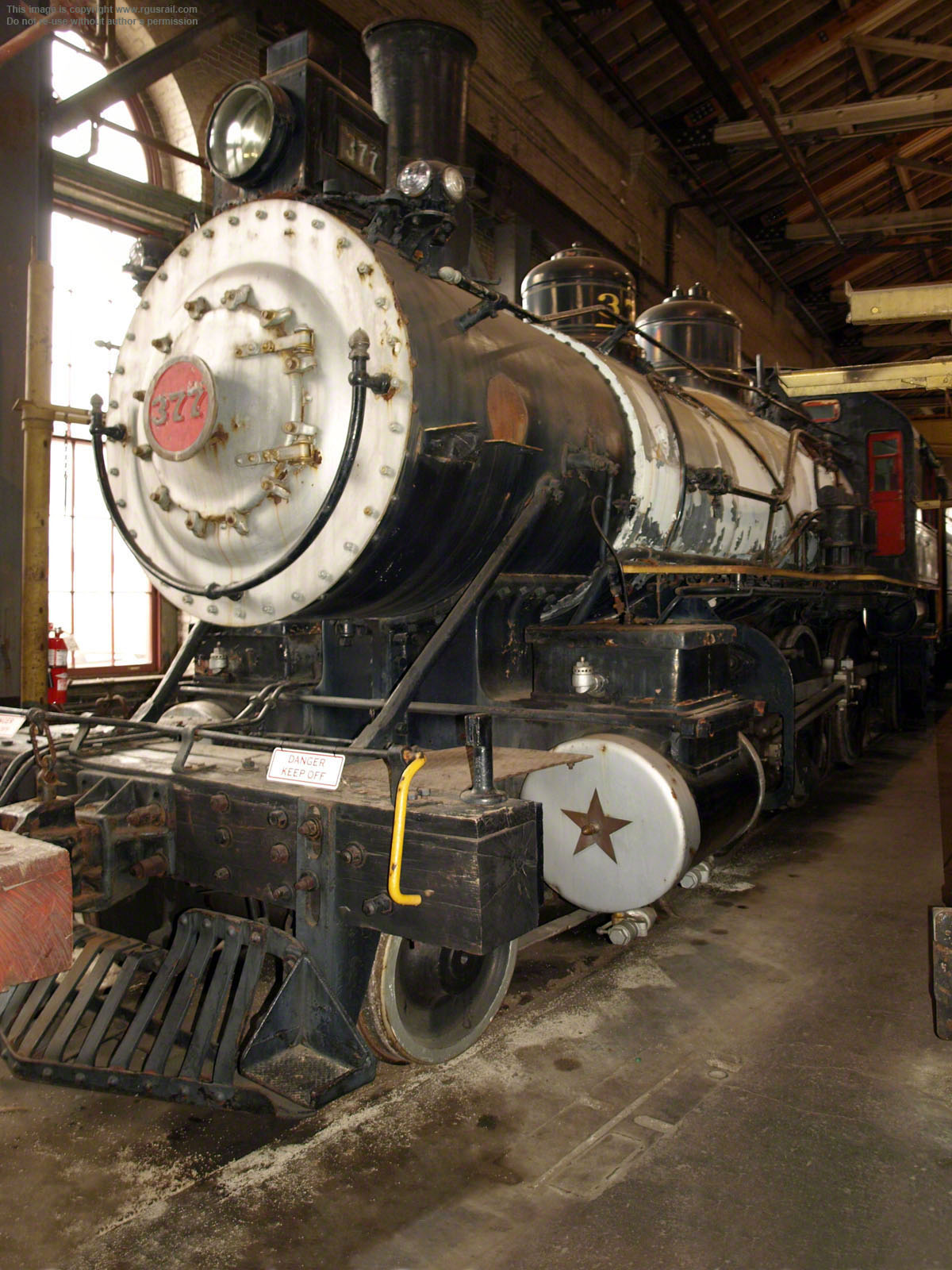
#377 is a Ten Wheeler (4-6-0)
type locomotive built by
Burnham, Williams & Co., in Philadelphia, an early incarnation of the Baldwin Locomotive
Works, for the Cincinnati, Richmond & Muncie Railroad in 1902 as #108.
Shortly after buying the locomotive, the R&MR was merged into the Chicago, Cincinnati & Louisville Railroad. In 1909, the CC&L went bankrupt and was subsequently purchased by the Chesapeake & Ohio.
During the 1920s, #108 was renumbered #1108 and, in 1923, became #377. In the 1930s, it transferred to Clifton Forge, VA, to work on the James River Line, hauling passenger and freight trains between Eagle Rock and New Castle on the Craig Valley Branch until retired in 1952.

Left, looking inside the cab from the fireman's side of the foot plate.
#377 weighs 143,500 lbs, 115,000 lbs on its 62" drivers. It has 19" x 26" cylinders and is equipped with Stephenson valve gear. With a 24.9 sq ft grate, 188 sq ft firebox and total heating surface of 2,352 sq ft, it operated at 180 psi, delivering 23,162 lbs tractive effort. The tender weighs 136,310 lbs light with a capacity for 12½ tons of coal and 7,000 gallons of water.

#377 was due to be scrapped, but the city of Logan, WV, asked if it could be "aged" for the anniversary celebration of the first C&O locomotive to arrive at the city in 1904. The C&O obliged by installing an oil headlight, flanged stack, cylinder head stars, a wooden pilot and an old style paint scheme. After the anniversary, C&O coupled it with ex-Hocking Valley wooden combine #409 for display and to work as a good will ambassador for the railroad.
It was occasionally steamed up before being permanently relocated to the museum in 1971. It is the oldest surviving steam locomotive to have operated on the C&O.


CO #490 was originally built by Alco in
1926 as an F19 class Pacific type locomotive (4-6-2), but it was one of five rebuilt as L1 class Hudson (4-6-4) types at the C&O's Huntington, WV, workshops in 1946. Four (#490-#493) were fitted with the yellow streamlining, which earned the rebuilt locomotives the somewhat unindearing nickname of "Yellowbellies", but these were major rebuilds and only the outer boiler shell was retained from the older locomotives.
Modifications included a new but otherwise similarly sized 281 sq ft
firebox, one-piece cast frames with integral cylinders and main air reservoirs, roller bearings on all axles and main and side rods, forty-one 2¼" boiler tubes to replace the original two hundred and twelve, one hundred and ninety five 3½" flues replacing the original forty-eight, a Type E superheater to replace the F-19's Type A increasing the superheating surface by 65% to 2,001 sq ft, raising the boiler pressure from 200 to 210 psi and a more efficient Worthington feedwater heater taken from the C&O's F-17
Pacifics.


Following WWII, the C&O was determined to revive falling passenger numbers and the four locomotives were designed to handle connecting services to the Chessie, a proposed new luxury service between Washington, DC, and Cincinnati, OH, to replace the George Washington.
The C&O ordered new fluted stainless steel passenger cars from Budd for the trains and invested in three new steam-turbine locomotives in 1947 and 1948 that were to be the motive power.


I am not usually a fan of streamlining, but there is something about #490's "Mohican" nose and fluted styling that appeals.


Above, the stainless steel tenders were also fluted and tapered at the top to blend with the new Budd cars. They weighed 355,300 lbs light with a capacity for 18,000 gallons of water and 28 tons of coal.
But this was increasingly an era of automobile and air travel and, as passenger numbers continued to decline, the C&O's plans to inaugurate the Chessie were abandoned. The steam-turbine locomotives were maintenance nightmares in any case, and were scrapped within three years. The four stylishly shrouded Hudsons were then assigned to regular C&O passenger services between Washington, DC, Newport News, VA, and Chicago, IL,

Above, the deck apron (top), stoker feed connection (centre) and radial buffer (bottom).
The L1s were heavier than the F-19s, 388,700 lbs compared to 331,500 lbs, and 202,500 lbs on their drivers compared to 200,000 lbs. With a combined heating surface of 6,415 sq ft. these coal burners delivered 49,237 lbs tractive effort.
The first two L1s were retired in 1953, and the second two followed in 1955. Three of the four streamlined locomotives were then scrapped, and #490 is the sole survivor and the only surviving streamlined Hudson type. It was donated to the museum in 1971 from the C&O Historical Collection.


Above, new 74" drivers were also fitted as part of the rebuild. These were carefully cross counter balanced for high-speed operation.
The L-1s had a 13' driver wheelbase, an engine wheelbase of 38' and an overall wheelbase (engine and tender) of
87' 9".
The F19s were built with Baker valve gear, but the rebuilt locomotives were fitted with Franklin Poppet valves. This accounts for #490's absence of the usual valve rods and levers.
The poppet valve gear for steam engines was invented by the Italian Arturo Caprotti in 1916.

Above, a trailing truck with a Franklin type E-I booster, operating up to 35 mph, was also part of the rebuild.


Above, the rebuild replaced the F-19's alligator type with multiple bearing crossheads.

Poppet valves used camshafts and poppet valves instead of pistons to provide much better control of steam entering and leaving the cylinders, much like internal combustion (motor vehicle) engines. The vertical lever visible just behind the back cylinder head in the photos on the right transferred movement from the crosshead to camshafts in the gearbox.
Poppet valves also gave a considerable
boost to tractive effort. Although the L-1's cylinders were of the same size as the
F-19's, tractive effort rose from 46,892 lbs to 49,237 lbs. They were also very smooth running: apparently, one C&O engineer discovered that it was only the dynamic augment of the locomotive exceeding its counter balancing speed that awoke him to the fact that he was touching 95 mph with six heavyweight cars.
Poppet valves date back at least to the 1770s, when James Watt used them on his beam engines in Great Britain. Frederick Ellsworth Sickels also patented a valve gear for double-beat poppet valves in 1842. After Caprotti refined the poppet valve, it then underwent further development on both sides of the Atlantic.


However, their internal complexity compared to the the external Walschaert or Baker valve gear made poppet valves unpopular.
They were challenging to maintain, problems were difficult to locate and, unfortunately, their final refinement came just as diesels were replacing steam power on US railroads.

Poppet valves were tried on a few US railroads, including Pennsy's T-1 Duplexes.

#490 is the only surviving US engine with poppet valves.


Twelve locomotive designs were also produced by a committee of representatives of the USRA, railroad owners and locomotive manufacturers, the closest the US railroads and locomotive builders ever got to standard locomotive types, and nearly one thousand nine hundred had been built by the time the USRA was disbanded in 1920.
Ironically, WWI was almost over when #4500 was ready for service on 4th July 1918. Like the other USRA designs, #4500 was sturdy, functional and popular with maintenance and locomotive crews. It was also popular with the railroad companies, and a total of six hundred and forty-one copies of the type were produced by different US railroads in the years after the war.
Built by Baldwin in just twenty days, "Light Mikado" type (2-8-2) Q3 Class #4500 was the first locomotive produced by the United States Railroad Administration (USRA). Created in 1917 in response to America's entry into WWI, the USRA nationalised the nation's railroad system in the interest of ensuring the most efficient operations possible.
Under the USRA, the nation's railroads were organised into three divisions: East, West and South. Duplicate passenger services were stopped, sleeping car services were cut back and extra fares applied to them. Uniform passenger ticketing was instituted and competing services on different railroads were cut back. Terminals, facilities and shops were shared.


Above, a view of #4500's cab. It was equipped with the latest technology of its time, including an automatic stoker.
The engine weighs 292,00 lbs, 220,000 lbs on its drivers. With a driver wheelbase of 16' 9" and a total wheelbase of 36' 1", it was built with 63" drivers but the B&O changed these to 64" soon after delivery. The locomotive has Walschaert valve gear and 26" x 30" cylinders. The grate area is 66.7 sq ft and the firebox is 286 sq ft. With a total heating surface of 4,659 sq ft, including 882 sq ft superheating, it operated at a boiler pressure of 200 psi delivering 53,869 lbs tractive effort.
The tender weighs 185,400 lbs light and has a capacity of 10,000 gallons of water and 16 tons of coal.
The B&O took delivery of a total of one hundred Q3s in 1918 (#4500-#4599). #4500 operated on the B&O's Ohio Division mainly hauling freight until it was retired in 1957. The last Q3 retired in 1959 and #4500 went
on display at the B&O Railroad Museum in 1964. It was accorded National Historic Mechanical Engineering Landmark status in 1990.


The "Heavy Pacific" (4-6-2) was another successful USRA design, from which the Baltimore & Ohio derived its P7 class. When I visited in 2004, #5300 was in the museum's rear yard.
#5300 was the first of twenty P7s built by Baldwin in 1927 and known as the "President" Class. They were the last mass purchased passenger steam locomotives to operate on the B&O. #5300 was named "President Washington" and was unveiled at the Fair of the Iron Horse in 1927. It is the only survivor of this class.
With 80" diameter drivers, the "Presidents" were built for speed and could easily reach 90 mph. There is one anecdotal story of a run over the New York Shortline Cutoff between Olney and Parkland Junction, PA, on which the speedometer was "glued to the maximum 95 mph reading".
The locomotives initially hauled the Royal Blue trains between Washington, DC, and Jersey City, NJ, but they were soon relegated to the western division by the B&O's early dieselisation in the 1930s with the EMC EA/EB units (EA/EB #51 is shown earlier on this page).


By 2008, #5300 had been moved into the car shop.
The "Presidents" were originally liveried in olive green with gold and red detail although, over the years, their names and livery were sometimes changed.


The original livery is more evident in the photos above although, before being retired in 1956, the colour scheme applied to #5300 was actually Royal Blue with a grey smokebox.
The "Presidents" underwent numerous modifications, including four different firebox designs. #5301-#5304 were streamlined to a design by Otto Kuhler for the prestigious B&O Royal Blue in 1937 and reclassed as P7d. They had new frames and all axles were fitted with roller bearings. Although the streamlining was removed in 1940, it was reinstated in 1946 when the four locomotives were assigned to the shortlived Cincinnatian from Baltimore, MD, to Cincinnati, OH (in 1950, the route was cut back to Detroit, MI, to Cincinnati, OH). Unfortunately, none of the streamlined P7ds have survived.


Above, views along #5300's 394 sq ft firebox.
The grate is 70.8 sq ft and the firebox has 81 sq ft of thermic syphons and 14 sq ft of arch tubes.

Above, a view looking along the boiler from the engineer's side. The locomotive weighs 326,000 lbs, 205,000 lbs on its drivers. The total engine
wheelbase is 37' 8" and the driver wheelbase is 14'. With a total heating surface of 3,846 sq ft, including 932 sq ft superheating, #5300 operated at boiler pressure of 230 psi and delivered 49,882 lbs tractive effort.
The tender weighs 218,000 lbs light, making a total weight of 544,000 lbs. The tender has a capacity of 11,000 gallons of water and 17½ tons of coal.

The view of #5300's backhead above reveals a somewhat parlous state, with the jacketing removed and the brake stand and controls gone, amongst other parts. The red button on the right plays a historical information about #5300.
The "Presidents" were built for speeds that would have been unattainable without the automatic stoker (the elevator pipe to the distributor in the firebox is in the middle at the bottom of the view above). The stoker was supplied by the Lower Company of Baltimore, MD, a short lived supplier of automatic stokers. The founders had worked for Standard Stoker and were sued by that company in 1931 for infringement of design patents.
Although an automatic stoker took care of feeding much of the coal to the firebox, a fireman still had to keep a regular eye on it, maintaining an even bed by filling any low spots manually, breaking up any clinkers that might form and shaking the grates to release built up ash to the ash pans.


Just behind the tender of CO #1604 is a
brass model of #5300 with cutaways
showing some of the internal workings. It was built by George Klein, one of the museum volunteers in 1995, and took 1,535 hours to complete

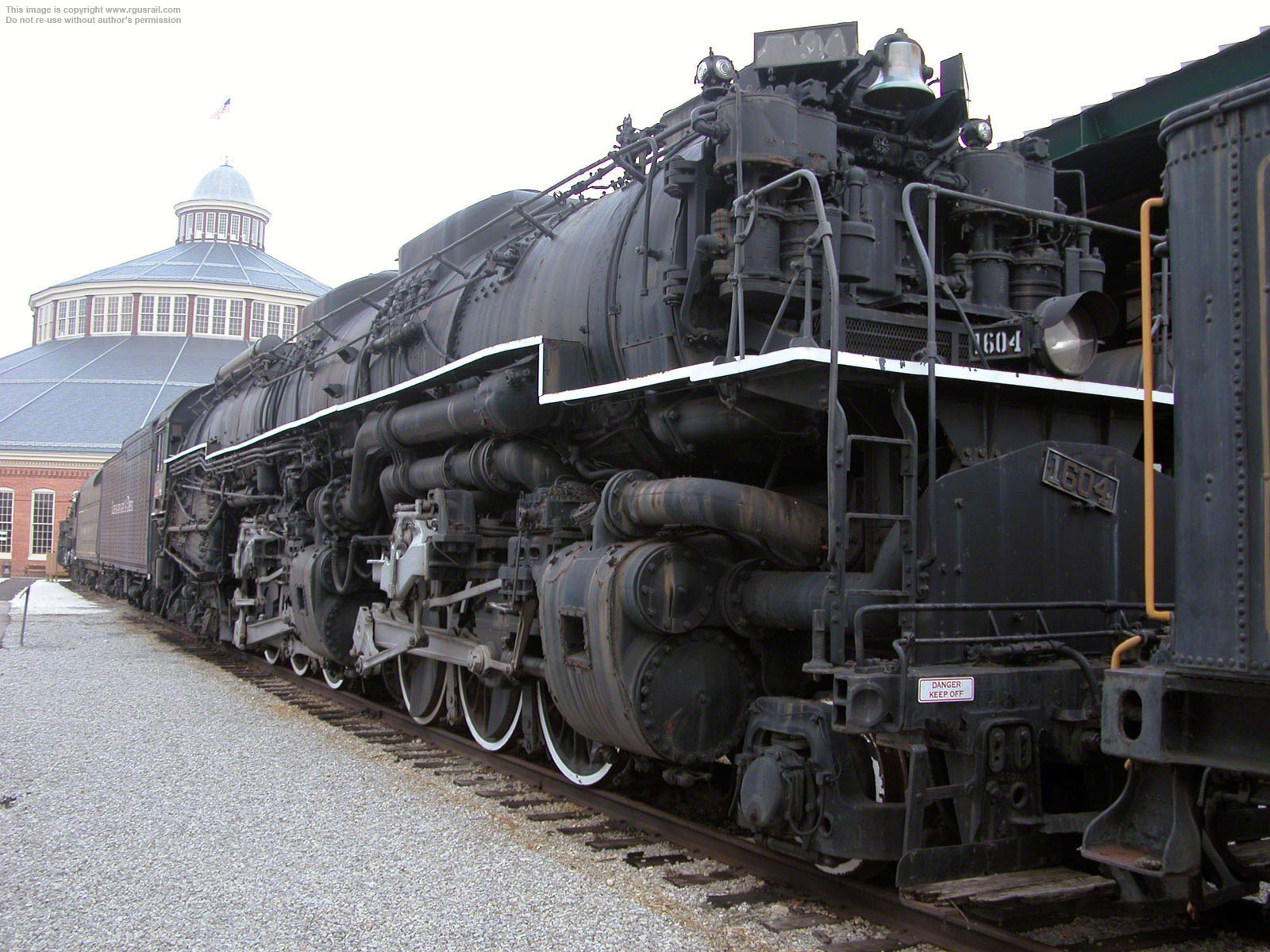
#1604 is one of sixty 2-6-6-6 Allegheny H-8 class locomotives built by Lima for the Chesapeake & Ohio from 1941 to 1948. When I visited in 2004, it was in the rear yard looking the worse for wear.
#1604 was part of the first order of ten locomotives. Eight almost identical locomotives were also supplied to the Virginian in 1945. They were designed for speeds in the region of 45 mph but could easily sustain 70 mph under the right conditions.

Above, the right rear cylinder shows the effects of resting outdoors.


When I visited in 2008, however, #1604 had been nicely repainted and moved into the car shop. You can see the only other surviving Allegheny, #1601, on the Henry Ford Museum page of this website.


In 2009, a couple of pieces of 4 x 2 had been attached to #1604 to brace a
partition along the adjoining track (on the right in these photographs). The views above also show the Allegheny's "flying pumps", centrally mounted headlight, angular shield, vertical ladders and very deep platform. Combined with the low-slung, snub nosed General Steel Castings pilot, these gave the locomotive its distinctive front-end.
The Alleghenies were designed to handle heavy grades over the Allegheny Mountains (the railroad's New River and Alleghany sub-divisions), but also worked from Russell to Toledo, OH, which had numerous short adverse grades, and hauled some passenger trains on the Mountain division (Charlottesville to Clifton Forge, VA).

Above, the right hand air brake compressor on the engineer's side.

Westinghouse supplied the two pumps, which took steam from the saturated side of the superheater header.
The handrails and ladder steps were originally painted white, as was
the radiator panel surround in some models.

Above, the feedwater heater cold water pump is just below the cab.

The Worthington Type 6½ SSA feedwater heater was installed in a mount at the front of the smokebox. It could return some 14% of the water used from the tender as condensate.
The hot water pump was located behind the air after coolers.

In the photo above, on the left, a view of the
rear left engine's third driver (note the size of the counter weight). Behind the driver is the 762 sq ft firebox supported by a six wheel trailing truck. The spoked trailing truck wheels are 43". The two pilot truck wheels are 36" and of solid design.
The trailing truck supports the 135.2 sq ft grate set entirely behind the drivers. The truck
has a lateral centering device supplied by the Timken Roller Bearing Company.
The trailing truck was actually designed to accommodate a booster, although this was never fitted to any of the Alleghenies.

This view along the engineer's side of the boiler shows the front end of the air reservoir tank at the upper left and the
two massive sand domes. #1604's reservoir line, train line and brake cylinder line run just below the running board. Beneath, is another air reservoir tank just above the right rear valve gear. The horizontal rods with the elbow lever at the upper centre of the photograph connect to the American type throttle at the front of the boiler.
The outside boiler diameter (i.e. beneath the cladding) is 109". It is fitted with
48 x 2¼" tubes and 278 x 3½" flues 23' in length supplied by the National Tube Company. A 118" long combustion chamber was added, and three siphons with a combined heating area of 162 sq ft were fitted to the firebox.
An Elesco Type E superheater was installed, which supplied 3,186 sq ft of heating surface bringing the engine's total heating surface to 10,426 sq ft. Operating at a boiler pressure of 260 psi, the locomotive delivered 110,211 lbs tractive effort.

Left front cylinder and Nathan automatic engine lubricator operated by elbow link from combination lever.

Above, the left front cylinder showing the steam supply (middle) and exhaust pipe (lower middle).
The four 22½" x 33" cylinders are all high pressure.

Above, the front engine, with left front cylinder, rear cylinder exhaust, steam line, Baker valve gear and main rod.

A close up of the left
rear cylinder showing
the steam supply (upper left), steam exhaust (upper right) and cylinder heads.
The small vertical pipe is to sand the rails.

Above, the left rear cylinder, Nathan automatic engine lubricator and multiple bearing crosshead.

Side view of left rear elbow link from the combination lever to the Nathan automatic engine lubricator.
A Detroit automatic valve lubricator is on the right side of the engine.

Above, rear engine, with Baker valve gear, main and side rods. An air reservoir tank is above the valve gear.

The drivers are 67" in diameter. All wheels were supplied by the American Rolling Mill Co., The driver tires were supplied by Alco.
The forged steel rods are of standard design.

Above, the water bottom tender was built with a six-wheel leading truck, but an eight-wheel trailing truck.

Above, the coal bunker. The tender had a
capacity of 25 tons of coal and 25,000 gallons of water.

Above, the firebox was fed by a Standard Stoker Company MB type stoker. A couple of the arch tube bricks are still in place on the syphons at the far end and, looming off into the darkness is the locomotive's massive combustion chamber.

Above, the grate was built by the Waugh Equipment Company.
You can see the rods connecting the grates to the shakers in the cab running horizontally in the lower part of the photo. Shaking the grates was usually the fireman's responsibility, although there were shakers on the engineer's side. It released ash and clinkers from the fire to promote better combustion.
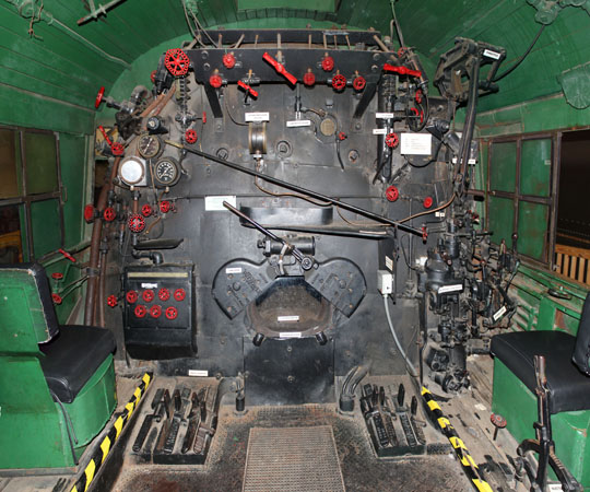
Hover your mouse over the photo to identify the main backhead controls.
1. Feedwater Control
2. Stoker Engine Control
3. Stoker Jets Control
4. Water Gauge Control
5. Turret Control
6. Dynamo Control
7. Cab Heat Control
8. Front Mech'l Lubricator Control
9. Rear Mech'l Lubricator Control
10. Injector Control
11. Passenger Car Heat Control
12. Feedwater Pump Throttle
13. Steam Heat Gauge
14. Feedwater Pump Pressure Gauge
15. Stoker Steam Jets Gauge
16. Boiler Water Sight Glass
17. Boiler Pressure Gauge
18. Low Water Alarm
19. Highest Point of Crown
20. Back Pressure Gauge (gone)
21. Throttle
22. Stoker Booster
23. Stoker Throttle
24. Stoker Jet Controls
25. Fire Door Actuator
26. Locomotive Brake Lever
27. Train Brake Lever
28. Reverse Lever
29. Steam Injector Lever
30. Rail Washer Valve
31. Grate Shaker Levers
32. Stoker Auger Access Door
Which was biggest/greatest/most powerful steam locomotive?
For somewhat obscure reasons (apparently because of regular but unco-ordinated tinkering with the design), the first Alleghenies were much heavier than the C&O allowance, and their weight was progressively reduced in following orders. The C&O actually sued Lima because of the weight difference and were reportedly awarded a settlement of $3,000,000 that effectively wiped out any
profit they might have made on the locomotives. As a result, the first Alleghenies were heavier even than Big Boys (778,000 lb vs. 772,500 lb). They also had a larger maximum boiler diameter (109" vs. 106½"), a larger smokebox diameter (102" vs. 95" tapering to 90") and longer boiler tubes (23' vs. 22').
However, if you check the photos of DMIR #229 on the Two Harbors Depot Museum page of this website, you'll see it is also signposted as an example of the world's largest steam locomotive. It was certainly the heaviest on its drivers (564,974 lb vs. 545,200 lb for the Big Boy) and had a higher tractive effort (140,000 lb vs. 135,375 lb) but it was nearly 8' shorter than the Big Boy with its tender, and the engine itself was almost 73,000 lb lighter.
The debate over the greatest steam locomotive is ongoing, and the conclusion depends on which aspect of locomotive weight and/or performance you consider. For example, you could argue that Norfolk & Western's Y-6 was the most powerful steam locomotive with its 170,000 lb tractive effort when running simple (you can see a Y-6a on the National Museum of Transportation, St. Louis Train Sheds page of this website).
Others include the N&W A class 2-6-6-4 in their
calculations, as much because of its versatility as its high gross tonnage (18,000 lb vs. the Allegheny's 14,000 lb). Eugene Huddleston includes the N&W A class, along with the UP Big Boy and C&O Allegheny in his World's Greatest Steam Locomotives, TLC Publishing, 2001. You can see NW A Class #1218 on the Virginia Museum of Transportation page of this website.


Maryland & Pennsylvania Railroad Inspection Car #101 was built by the Buick Motor Corporation in Detroit, MI, in 1937. It was initially owned by the Harkins Funeral Home in Delta, PA.
The railroad rebuilt the car in 1942, with flanged wheels, a track sander for slippery rails, a pin-swivel truck in front, and a handbrake controlled by the steering wheel. It was used to carry officials on maintenance of way inspections. At some point, a two-way radio was installed in #101 to test radio communications between locomotives and stations.


This kind of car is actually an early version of the "highrail" pickup truck, now widely used by US railroads.
At some point, #101
was retired and
donated to the
museum.
You can see another car of this type, a 1947 Dodge four-door sedan equipped with special wheels for the Milwaukee Road on the Mid-Continent Railway Museum page of this website.
Related Links:
Baltimore & Ohio Railroad Museum Website
Chesapeake & Ohio Historical Society
Story of the American Freedom Train
Steamlocomotive.com on the Largest Steam Locomotives
Send a comment or query, or request permission to re-use an image.
Patrick Dorin's Chesapeake and Ohio Railway was published by the Superior Publishing Company in 1981 (click on the cover to search for this book on Bookfinder.com).
Below, Eugene L. Huddleston and Thomas W. Dixon Jr. have written an excellent book on C&O's H-8, The Allegheny, Lima's Finest, published by Hundman in 1984 (click on the cover to search for this book on Bookfinder.com).